Three Bearing Crane Hoist Drive Shaft Analysis Example
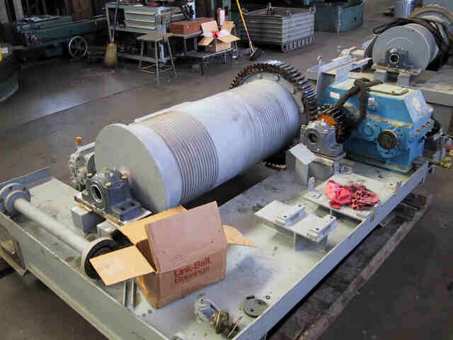
Below is shown a Crane Trolley
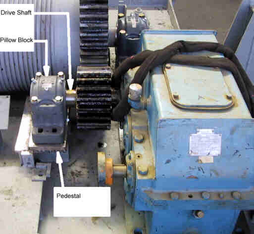
The picture below shows the gearbox drive arangement. The drive shaft is supported by three bearings, two within the gear box and the third with an external pillow block.
The objective of the analysis was to perform a fatigue analysis of the drive shaft with customer requirements of a safety factor of 1.5 against the requirements of ASME B106.1M. An additional objective was to determine the limits of alignment of the pillow block to the shaft to meet this safety factor requirement.
Analysis Model
FEA Modeling was used to determine the loads along the shaft. The trolley structure was modeled with shell elements, and the drive shaft was modelled with beam elements. The full trolley structure was modelled because deflections of the pillow block pedestal relative to the gear box mounting play a significant role in the loads that the shaft sees. Previous analysis of the shaft had assumed that the pedestal mount was perfectly rigid and resulted in underestimated shaft loads.
Initial Analysis indicated that under any pillow block shimming condition, the shaft loads exceeded the allowables. Measures were taken to stiffen the load path between the pillow block pedestal and the gear box mount, which had previously been quite flimsy.
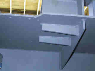
Old Pedestal Substructure
FEWeld was used to rapidly size these welds from the FEA Results:
Results
FEA Stresses
The Safety Factor Calculations derived from the FEA Beam Element Loadings: